6 | Cab Hardware Installation
This section covers installation of operator interface components and optional control inputs.
Required:
- Arm/Engage Switch
- Tablet
Optional:
- Joystick
- Tractor CAN Connection
- 6.1 | Arm/Engage Switch Installation
- 6.2 | RuggON Tablet Installation
- 6.3 | Joystick Connection (Optional)
- 6.4 | Tractor CAN Connection (Optional)
6.1 | Arm/Engage Switch Installation
The COMMAND Arm/Engage Switch is used by the operator to both Arm/Disarm ECU control outputs, and also to Engage/Disengage automatic control mode.
Mounting Location
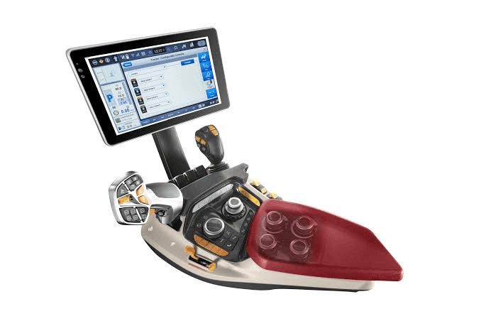

The Arm/Engage Switch should be mounted close to the operator's typical hand resting around the armrest for easy access to Engage or Disengage COMMAND's automatic control mode.
Ideally there may be a spare switch position in the armrest as shown below, but if this is not the case then a suitable bracket or enclosure will need to be added to the side of the armrest for example, to provide somewhere for the switch to be mounted.
Installation Steps

- Mount the switch near the operator’s armrest for easy access.
- Install the switch into an available switch cavity or bracket.
- Connect the T3H-C003 adapter to the T3H-C004 switch.
- Insert the adapter into the mounting location and pull through until the switch is close to the panel.
- Insert the switch into the mounting location and ensure it is seated correctly.
- Connect the T3H-C003 adapter to the T3H-C006 cab breakout harness.

Functionality (Operation)
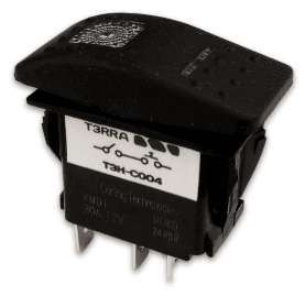
The switch has a configuration of OFF-ON-(ON). While in the OFF position, the ECU is disarmed and will not activate outputs or send hydraulic flow commands. The OFF position LED indicates that the ECU is powered.
When moved to the middle ON position, COMMAND is Armed and prepared for sending output signals or hydraulic flow commands. If using a joystick, COMMAND must be armed before the ECU will move the hydraulics.
Once in the middle ON position, the operator can then momentarily push into the third (ON) position, which toggles automatic control mode on or off. Please note that automatic control will only Engage once appropriate conditions are met. The idea here, is that once armed the operator may press the momentary button as needed to Engage or Disengage automatic control depending on their requirements.
IMPORTANT: In the event of an emergency, the operator should switch the Arm/Engage switch to the OFF position to completely disable movement of hydraulics. Please also note that Disarming COMMAND will also disable joystick functionality.
6.2 | RuggON Tablet Installation
This section covers installation of a typical RuggON tablet supplied by T3RRA, but these instructions are also relevant to those opting to use their own tablet PC.
Tablet Mounting Options
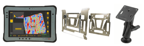
The tablet must be mounted somewhere in the cab where the operator can maintain good visibility of the screen.
Ensure the tablet does not obstruct operator visibility while driving.
Installation of the tablet for Level COMMAND is carried out in the same fashion as for any other T3RRA software installation. We highly recommend the RuggON PX501 or SOL7 as a tablet computer solution for use with Level COMMAND and provide various accessories for mounting them in the T3RRA Shop.
Mounting the Tablet
- Fasten the square silver tablet VESA plate to the square black RAM arm VESA plate.
- Using a suitable RAM mount or adapter bracket, create a mounting point for the swivelling RAM arm and fasten it to the tractor cab.
- Position the VESA plate appropriately so that the tablet can be slotted into and removed from the mount easily when required.
- Fasten the larger silver tablet plate to the back of the PX501 using the provided screws.
- The tablet is now ready to be slotted into the VESA plate on the black RAM arm and repositioned to the correct viewing angle.
- The tablet is now ready for connection to COMMAND.
Connecting the Tablet to COMMAND
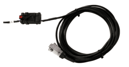
- Using a T3H-T001 or T3H-T002 cable, connect the 12-way AMPSEAL connector to the matching red and black AMPSEAL connector on the T3H-C002 ECU breakout harness.
- Run the serial cable along the tractor cab wall neatly and fasten to any available points using zip or twist ties.
- Connect the silver DB9 right angled (RA) or straight connection to the tablet and then secure the connector screws using a small screwdriver.
- Bundle and tie up any extra length of cable somewhere out of the way.
6.3 | Joystick Connection (Optional)
Overview
In most cases the manual control of hydraulic functions are already available (e.g. when using existing tractor auxiliary valves). In some limited cases it may be necessary to add operator control for hydraulic functions, e.g. when using an additional valve module, or using direct PWM operation of hydraulic valves from the COMMAND ECU. In these situations, two options are available: An analog joystick, or a J1939 CANBUS joystick.
If using a compatible analog or J1939 CANBUS joystick, this can be connected to the T3H-C002 directly or via a joystick extension harness.
- Ensure the joystick is fitted with an 8-way Deutsch DT plug (DT06-8S).
- Mount the joystick in an appropriate location in-cab according to manufacturer mounting instructions.
- Connect the plug to the connector labelled “Joystick” on the T3H-C002 harness.
- Verify correct pin alignment before connecting.
See below for the pin positions and connector information noting that this is the receptacle on the T3H-C002 ECU breakout harness.
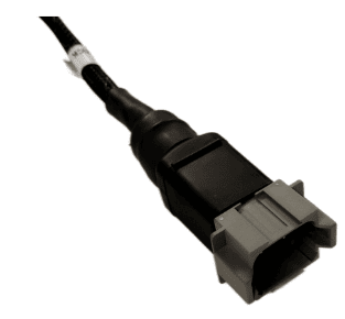
Mating joystick connector parts:
- Connector: DT06-8S / DT06-8SA
- Contacts: 1062-16-0122 or AT62-16-0122
 Analog Joystick Installation
Analog joysticks from brands such as APEM, Parker, Suregrip Controls or Danfoss can be connected to the system and used to manually control one or both available functions, e.g. Height and X-Slope.
Analog Joystick Specification Requirements
- Expected output range: 1.0 - 4.0V
- Expected resting voltage: 2.5V
Analog Joystick Connection
The T3H-C002 ECU Breakout Harness has an 8-pin joystick connection available that can be used to provide switched 12V power and access to the analog joystick signal inputs. Generally, Joystick Axis 1 and Joystick Axis 2 should be connected to the Y and X axis of the joystick respectively.
1. Connect joystick to the 8-pin joystick connector on the T3H-C002 harness.
2. Connect power to Switched 12V and GND.
3. Connect signal outputs to joystick axis inputs.
4. Verify voltage range is within 1.0–4.0V.
NOTE: The Joystick Axis 3 signal is currently not in use - COMMAND is currently capable of controlling 2 functions for manual control.
Analog Voltage Signal Requirements
The joystick output voltage must be centred at 2.5V when not being manipulated, and should lower in voltage to a minimum of 1V in one direction, and to a maximum of 4V when moved in the opposite direction.
IMPORTANT: 0-5V Output range joysticks cannot be used with COMMAND, as input voltages of 0V and 5V are assumed to be a short circuit to ground or 5V respectively.
J1939 / CANBUS Joystick Installation
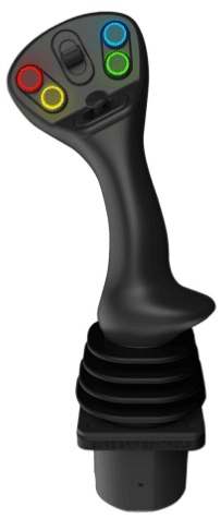
A ruggedised multifunction J1939 CANBUS joystick with suitable output messages can be connected to the joystick connection on COMMAND harnessing to provide manual operator control of the scraper.
A J1939 joystick such as the APEM HF Series J1939 joysticks can be connected to the system and used to manually control the two available functions, e.g. Height and X-Slope.
Interface Parameters
- Baud rate: 250 kbps
- Transmission repetition rate: Recommended 10 hz or higher
Connection
The joystick connector on COMMAND harnessing can provide a 12V DC supply for the joystick, and then receive joystick position messages back via CANBUS. The COMMAND ECU has been programmed with J1939/ISO basic joystick message types to provide selection between fore/aft, left/right and twist axes for each of COMMAND's control functions. See below for pinout information.
1. Connect joystick power to Switched 12V and GND.
2. Connect CAN HI and CAN LO to ISOBUS HI and LO.
3. Verify communication at 250 kbps.
4. Confirm joystick inputs are detected in Level COMMAND.
Expected Message Protocol
Message 1 - BJM1 - PGN 0xFDD6
Primary X-axis or Y-axis can be assigned to COMMAND function 1 or function 2.
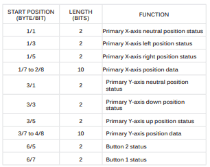
Message 2 - EJM1 - PGN 0xFDD7
Primary Z-axis or Y-axis can be assigned to COMMAND function 1 or function 2.
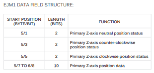
For more assistance in setting the selected joystick type and joystick axes within Level COMMAND, please refer to the Level COMMAND manual.
6.4 | Tractor CAN Connection (Optional)
Overview
COMMAND can be connected to a 250 or 500kbps Tractor CANBUS if present, allowing the ECU to read tractor data directly from tractor systems including parameters such as engine load, hydraulic oil temperature, wheel speed and instantaneous fuel usage. This data can then be displayed in the widgets in Level COMMAND in real-time, and is also used in the background for certain control features.
Connecting to an incorrect CANBUS, or having COMMAND's Tractor CAN port set to the incorrect baud rate may cause tractor system errors.
Required Parts
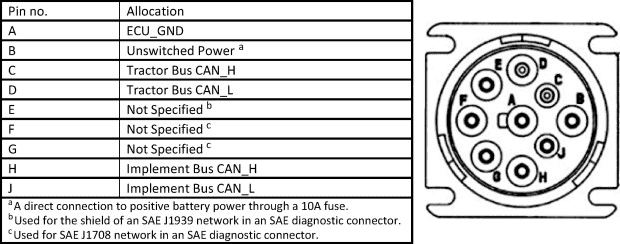
A port replicator is included on the T3H-M001 adapter so that other devices may be connected to the diagnostic connector when necessary without removal of COMMAND harnessing.
If the tractor has a Type I diagnostic connection, T3H-X004 should be added to maintain the Type I connection for the tractor.
Type I J1939 Diagnostic Connection (Black)
- T3H-M001 - COMMAND J1939 Diagnostic Adapter (Green)
- T3H-X004 - J1939 Type I-Type II diagnostic adapter
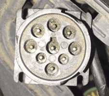
Type II J1939 Diagnostic Connection (Green)
- T3H-M001 - COMMAND J1939 Diagnostic Adapter (Green)
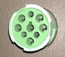
Connection Process
- Connect the T3H-M001 adapter to the appropriate diagnostic plug in the cab of the tractor.
- Connect the T3H-M001 adapter to the T3H-C006 Cab Breakout Adapter.
- If appropriate tractor data is present on the tractor bus, COMMAND will begin reading the data and providing it to Level COMMAND software.
- Check whether any new widgets have appeared with new data in the Widgets menu of Level COMMAND.