4 | Pre-Installation Requirements
Tractor, power and ISOBUS / CANBUS requirements for the usage of COMMAND
4.1 | Overview
All requirements in this section must be confirmed before installing the COMMAND system.
Failure to meet these requirements may result in improper operation or system damage.
Confirm the following before proceeding:
- Tractor compatibility
- Power supply suitability
- Communication interfaces (ISOBUS or CANBUS, RS232 NMEA 0183)
Details for each requirement are provided in the following sections.
4.2 | Tractor Requirements
Tractor Requirements
COMMAND's tractor requirements are as follows:
- Provide a suitable power supply as specified in Section 4.3.
- Have compatible SCVs or auxiliary control valves
- The tractor does not need to be ISOBUS-equipped; however, upgrading to ISOBUS is strongly recommended to provide the necessary connections (e.g. implement breakaway connector).
- Be capable of manual implement control.
- Be in good working condition with fully functional hydraulics.
If any requirement in this section cannot be met, installation should not proceed.
Implement Compatibility
Supported Implement Configurations
COMMAND is currently suitable for use with the following types of implements:
- Implements with a single hydraulic height control function and a single receiver, i.e. requiring a single valve. This includes implements with multiple height cylinders if the cylinders are linked together and controlled by the same valve. e.g. a basic tractor-pulled bucket scraper.
- Implements with a single hydraulic height control function, single receiver, and a single cross-slope/tilt control function, i.e. requiring a single separate valve for each (2 total). e.g. JN&R tractor-pulled scraper with cross-slope / tilt cylinder.
Future Configurations
- Implements with a single hydraulic height control function and dual receivers, i.e. requiring a single valve for height control and a single valve for cross-slope control with both a left and right implement mounted receiver.
- Tandem implements (convoy) each with a single hydraulic height control function, i.e. one valve controls front scraper height and another valve controls rear scraper height.
- Implements with two separate hydraulic height control functions, i.e. two separate valves are required to control each side of the implement. e.g. grader-style blades with independent left/right control.
- Two implements towed in tandem with a single height control function each, i.e. requiring one valve for each implement. e.g. two basic bucket scrapers towed in tandem.
Implement Definitions
The naming conventions below will help to avoid confusion later:
Single implement - One single blade with one receiver positioned in centre (single-axis or dual-axis) (May or may not be accompanied by IMU).
Tandem implements - Two blades in front/behind one another as a train, each with a single receiver positioned in the centre (single-axis control only).
Dual receiver - One single blade with two receivers positioned on the left and right sides of the blade for dual-axis control. The tilting point is assumed to be the centre of the blade edge, in the middle of the two receivers.
4.3 | Power Requirements
A switched 12V DC power supply with a minimum capacity of 10A is required.
The harnessing system has been designed to provide flexibility in sourcing 12V DC switched power depending on where the ECU is mounted, and where sources of protected 12V DC power are freely available.
The following power supply options are supported:
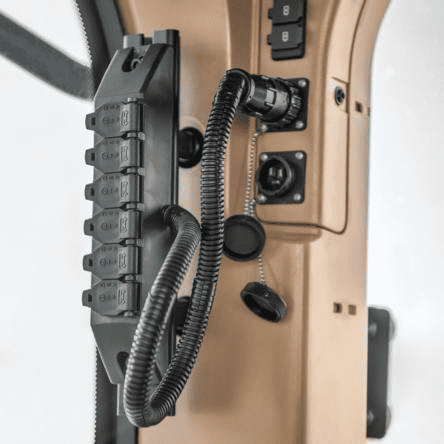
Cab Convenience Sockets
COMMAND can be powered using an available cab convenience power socket along with the T3H-F001 Power Adaptor provided by T3RRA.
NOTE: A minimum of two cab convenience sockets are required in total if providing power to COMMAND and implement harnessing, and a RuggON tablet. Three are required if adding an ISOBUS breakaway connector that requires a convenience power connection e.g. JD ISOBUS plug kit.
If fewer than two convenience ports are available, another power option may need to be used for COMMAND or the tablet.
WARNING: Convenience power supply sockets should be load-dump protected and fused appropriately within tractor electrical systems, and generally are but it's always best to make sure.
 |
|
Using a Constant Power Harness
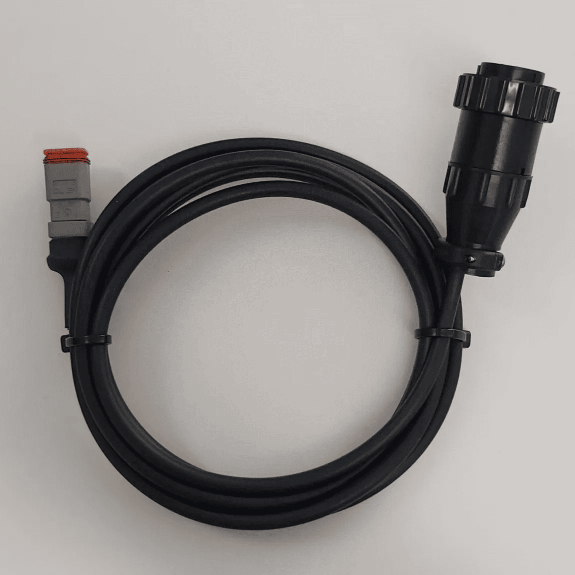
The Constant Power Harness (CNH 115-0172-397/8 OR JD BPF10403/4) can be connected to the COMMAND harnessing system at connector C6 on the T3H-C005 exterior breakout harness.
NOTE: The Constant Power Harness may not possess its own fusing, but a fuse is supplied on the T3H-C005 harness to protect against electrical faults.
Connection can also be made directly into the T3H-C002 EXT branch (Connector C6) if the T3H-C005 is not required but the aforementioned fuse must still be added for appropriate protection using a T3H-F003 Inline Fuse Adapter.
Providing a Custom Power Connection
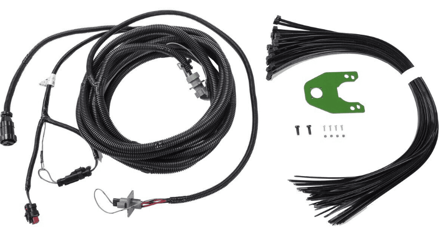
A custom connection to switched 12V power can be made using the T3H-F002 Power Adaptor (DT06-2S & Loose Wire Ends). The installing technician must provide the appropriate connections / terminations depending on their own requirements.
NOTE: Avoid routing power cables near high-current or noisy signals if possible (e.g. alternator).
WARNING: The power supply must be rated and protected appropriately for the application!
Custom Power Supply Requirements
If a custom power source is used, it must meet the following requirements:
| Description | Nominal Range / Rating | Notes |
| Supply Voltage (V) | 9-32V DC | Ripple/noise ≤ 100 mV peak-to-peak recommended; ensure DC/DC converters are well-filtered. |
| Supply Current (A) |
1A for general ECU operation plus 2A per proportional solenoid in use |
Depends on connected loads, MCU, sensors, and interfaces. |
| Power Supply Protections |
Overvoltage protection
|
Must be protected against load dump, inductive spikes, and cranking via TVS diodes or suppression circuits.
Transient protection required (TVS diode, suppressor per ISO 7637-2). |
|
Overcurrent protection |
Must include a fuse or circuit breaker rated to a maximum of 10A. |
4.4 | ISOBUS Requirements
COMMAND does not explicitly require the tractor to be fitted with an ISOBUS system to operate; however, we strongly recommend taking the opportunity to upgrade any tractor to be used with COMMAND to be ISOBUS capable as well, thereby future proofing for other future devices at the same time. ISOBUS / CANBUS harnessing may also be mandatory depending on choice of GNSS receiver.
ISOBUS / CANBUS GNSS Data
COMMAND may make use of the ISOBUS to read GNSS data of NMEA 2000 or StarFire message formats, which will be present and readily available to the COMMAND ECU if both the ECU and the GNSS receiver are connected to the ISOBUS.
ISOBUS Auxiliary Valve Control
COMMAND may also make use of the tractor ISOBUS when performing control of the electrohydraulic valves. Messages are sent to a tractor hydraulic controller over the ISOBUS in some configurations. Usually, if the tractor's hydraulic controller is capable of control via external messages, the machine will already have ISOBUS harnessing and functionality.
ISOBUS Overview
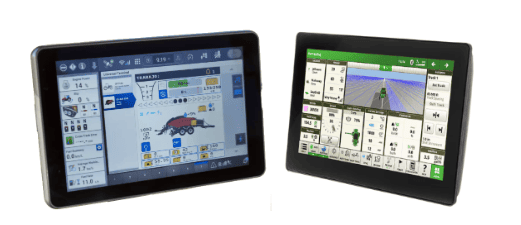
ISOBUS is a standardised CANBUS communication protocol that enables communication between tractors, implements, and control systems. This system simplifies operations, reduces clutter, and improves efficiency by allowing operators to control multiple implements from a single interface.
A typical ISOBUS setup will often include an ISOBUS terminal display along with various different ISOBUS harnesses that set up the standardised harnessing and messaging framework on the machine. Other types of ISOBUS compatible devices can then be added for all kind of functionality including auto-steering, automated land levelling, automated planting/seeding/spreading/spraying and more.
Next Step
If all requirements in this section have been met, proceed to Section 5 | ECU Installation & Mounting.